

From practice: MELARECON as an I/O device
Hello and welcome to the “From practice” series. Today I would like to show you how you can use our MELARECON as a CANopen I/O device. As you already know, every product development consists of one and the same core. This means that you can recreate this example with any MELARECON. I use our MELARECON IO in this project. In addition to a few additional graphical live tiles and a few presettings, this basically only consists of the actual core and is therefore optimally suited as a complete CANopen node. But enough said and off to practice. Let’s take a look at my test setup together:
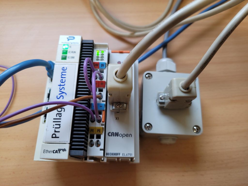
PLC control
In this example I use a CX8010 from Beckhoff. However, I do not use the TwinCAT-PLC, but the Soft-PLC S7-315-SD from IBHSoftec. This enables me to program with Siemens TIA Portal or Step7. I connected an EL6751 bus coupler to the CX8010, which is a CANopen master. I connect the bus coupler to a small box with a serial SUB-D9 cable in order to be able to get out the CAN-L, CAN-H and CAN-GND pins.
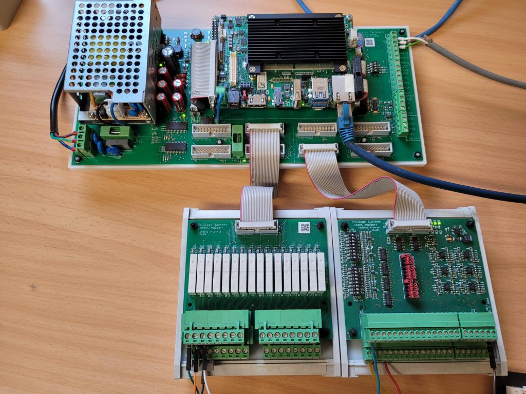
MELARECON IO
I connect the now open lines of the bus coupler to the CAN2 connection of my MELARECON IO. I have also connected an analog input card and a digital output card to the MELARECON mainboard. I connected both the PLC and the mainboard to the network.
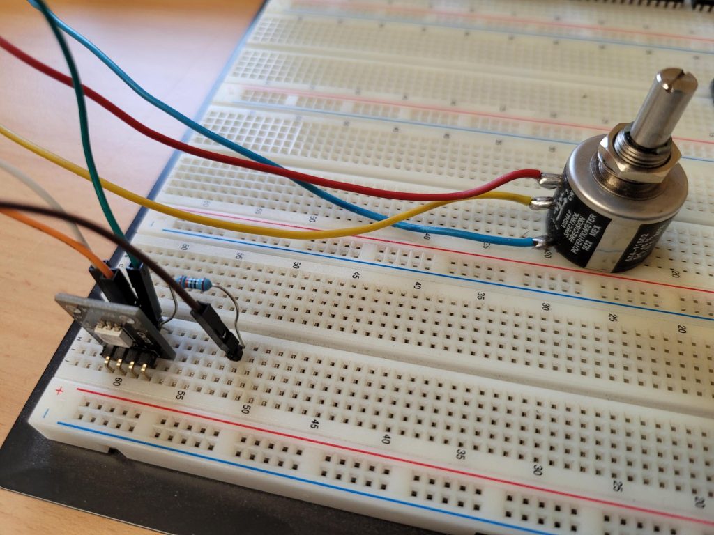
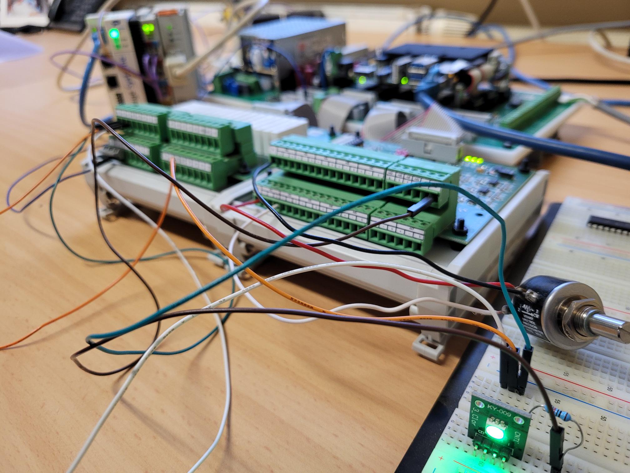
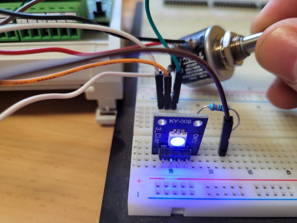
Signal generator and display as LED
I connected a simple potentiometer to the first input of my analog input card. I supply the potentiometer with 5V. I also use the first three digital outputs to control an LED with RGB channels. I supplied the potential-free outputs with 3.3V. You can find these at pins 17 or 19 of the slots for digital input cards.
Project goal
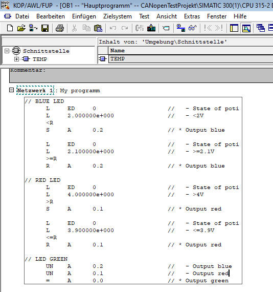
In this example I want the blue LED to be driven below an input voltage of 2V. Above 4V the red LED should light up and in the areas in between the LED should light up green. From a technical point of view, such an implementation should be feasible for every PLC programmer.
Configuration of the MELARECON
Like every MELARECON, the MELARECON IO can also be operated via VNC. The MELARECON display is therefore not required for our example. If you connect to the device, you will already be able to see the following views on the start screen.
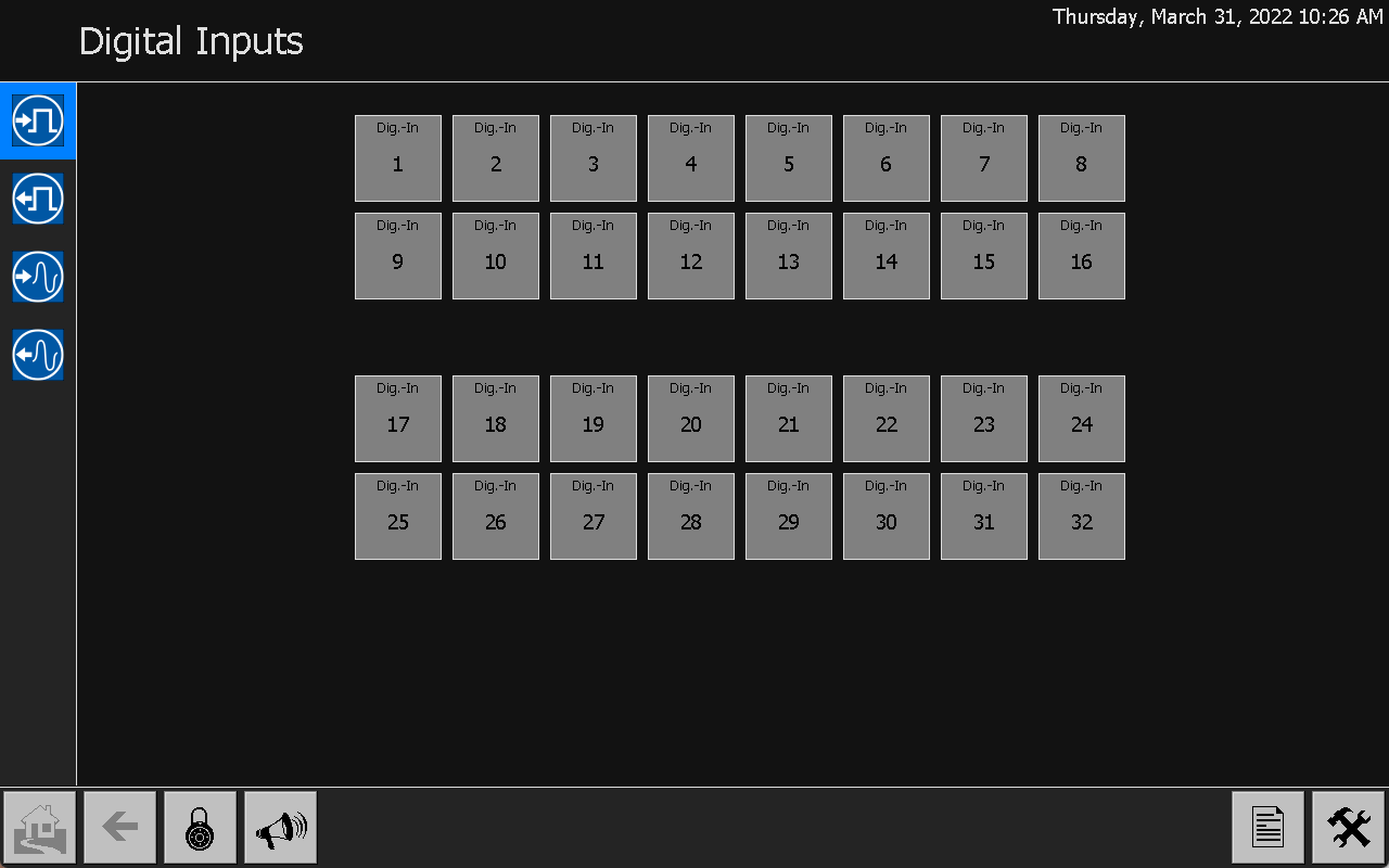
MELARECON IO start screen 1: Digital inputs
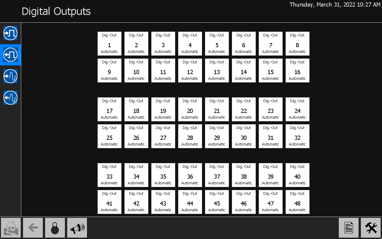
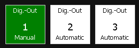
MELARECON IO start screen 2: Digital outputs
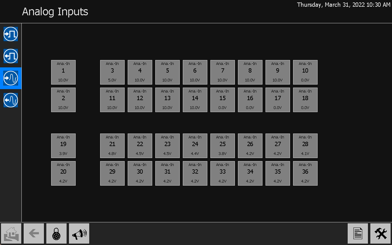
MELARECON IO start screen 3: analog inputs
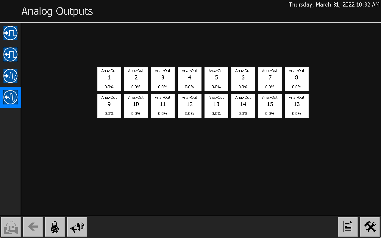
MELARECON IO start screen 4: analog outputs
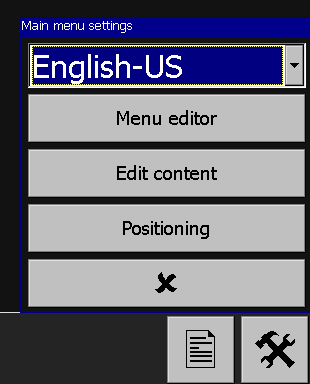
Change of language at MELARECON
With the views on the start screen you can test the function of your actuators and sensors directly. In the view of the digital outputs, you can set the outputs to manual mode by clicking on the first three channels. The first click sets the output to OFF. The next click sets the output to the ON function. Another click sets the output back to automatic.
The function of the analogue input can also be tested directly. Switch to the analog inputs view. Channel 3 shows the current input voltage. Now you can change the signal with the potentiometer.

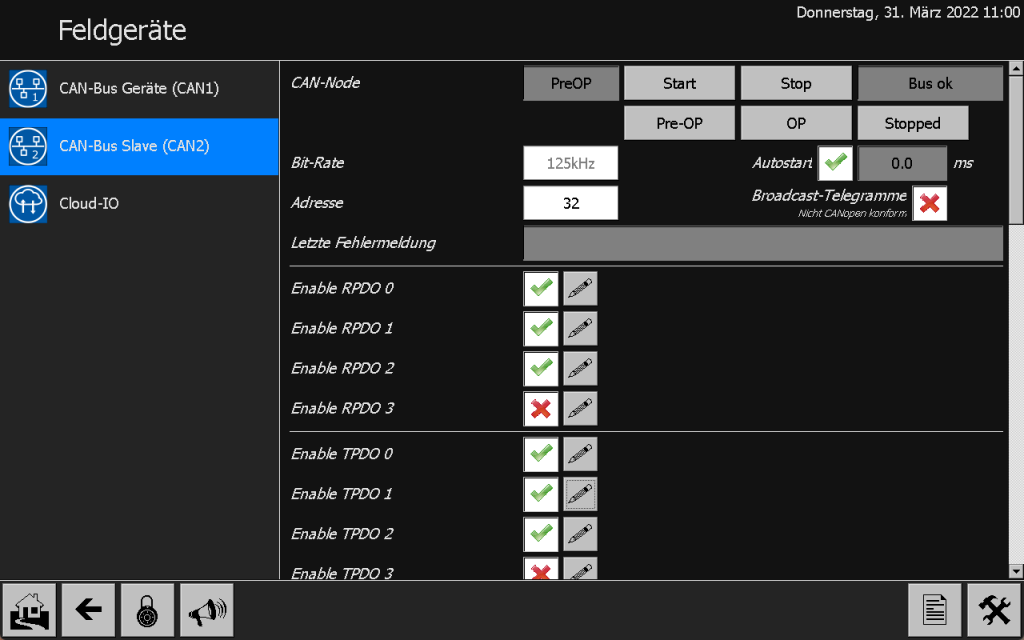
Now I change in the installation menu to “I/O configuration/field devices/CAN bus slave (CAN2)”. You’ll see that the bus port is already up and running at a bit rate of 125kHz. You can change the bit rate by pressing the “Stop” button. If you have made the desired setting, you can start the node again. Under the “Address” setting you can configure the bus address of the device. The default is 32.
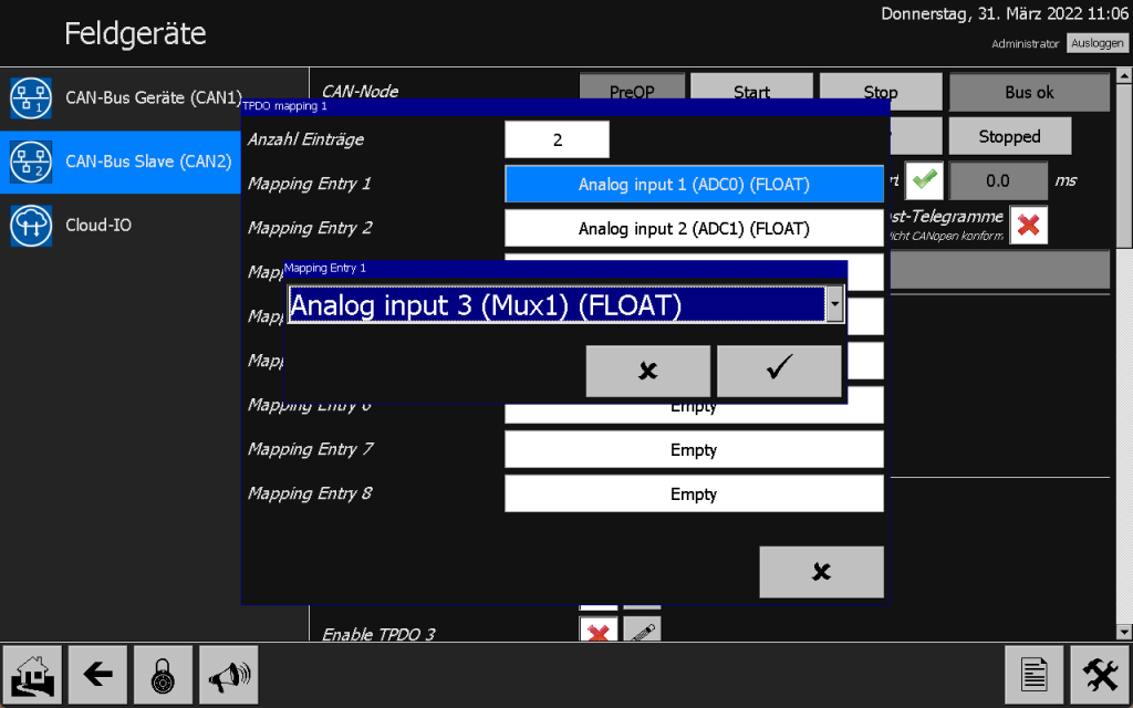
I would now like to change the PDO of the MELARECON IO. By default, the multiplex channels are transmitted in TPDO1 and TPDO2. Here I would like tor use the analog input 3 to be transmitted with TPDO1 instead of the direct ADC input. To do this, I open the settings using the button next to TPDO 1 and change the setting to “Analog input 3 (Mux1) (FLOAT)”. The EDS file prepared by us therefore still fits.
For our small example project, these are all the necessary settings. In the next step we take care of the configuration of the PLC.
Configuration of TwinCAT
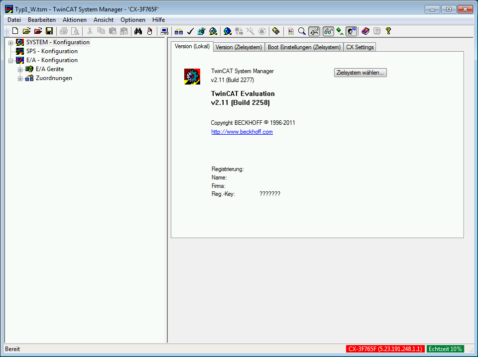
In order to be able to configure the CX8010, we need TwinCAT 2 from Beckhoff. To do this, I start the TwinCAT System Manager and create a new project.
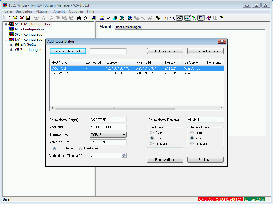
Now select “Select target system…” and go to “Search (Ethernet)” in the following dialog. I now run a “Broadcast Search” and get a list of all CX devices on the network. I select my own device and click the “Add route” button. You can then close the dialog and select your device in the dialog below.
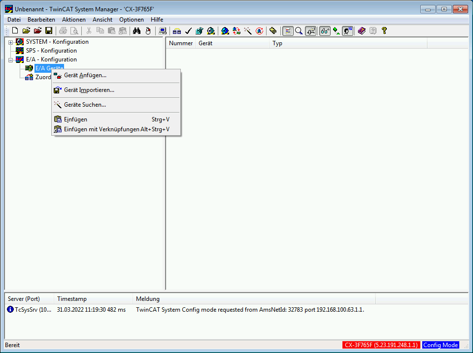
In the next step, I activate the config mode, for automatically read out the configuration of the CX8010. Config mode can be started via the “Actions / Start/Restart TwinCAT in Config mode” menu. Now, by right-clicking on I/O devices, I can select the “Find devices…” menu item in the context menu.
Now TwinCAT should read out the configuration automatically. Follow the instructions. If you are asked for the baud rate for the bus coupler, make sure that you set the same bit rate here as you selected on the MELARECON.
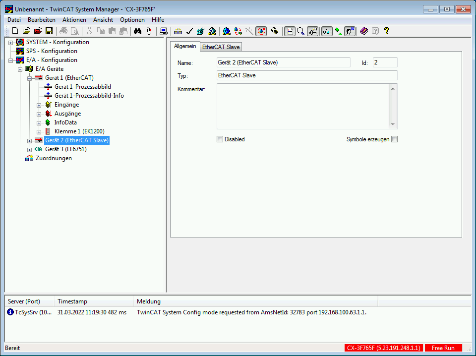
A separate device has now been added for the bus coupler. In the context menu of this device, select the “Append Box…” item. In the following dialog, select “CANopen Node” at the very bottom under “Miscellaneous” and confirm your selection with “OK”.

The new node has now been added. In the context menu of this new device I select “Load PDOs from EDS file…” and select the appropriate EDS file for our MELARECON. TwinCAT now automatically adopts the PDO settings from the selected file. Further settings for the new node can be found under the “CAN Node” tab of the device. Here you can, for example, enter the correct address. Of course I choose the ID 32 here.
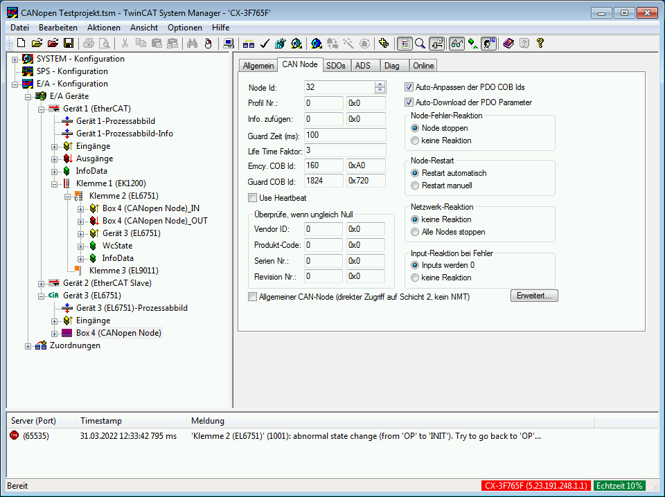
Additional parameter settings can be made on the SDOs tab. The interrupts for the analog inputs are deactivated in the default settings of the MELARECON IO. Therefore I add a new entry here for index 0x6423; Subindex 0 with the value 1. This activates the transmission of analog values using PDO. By default, all analog input channels are configured to transmit their ADC input value. This corresponds to a value between 0 and 3.3V. For this I make another entry for index 0x4200; Subindex 3 with the value 1 for 0..10V. Further initializations can also be carried out here. For example, it would make sense to activate the guarding to switch off the outputs if the PLC should fail. Furthermore, a minimum change can be configured for each analog value before an interrupt is even triggered. All setting options can be found in the documentation.
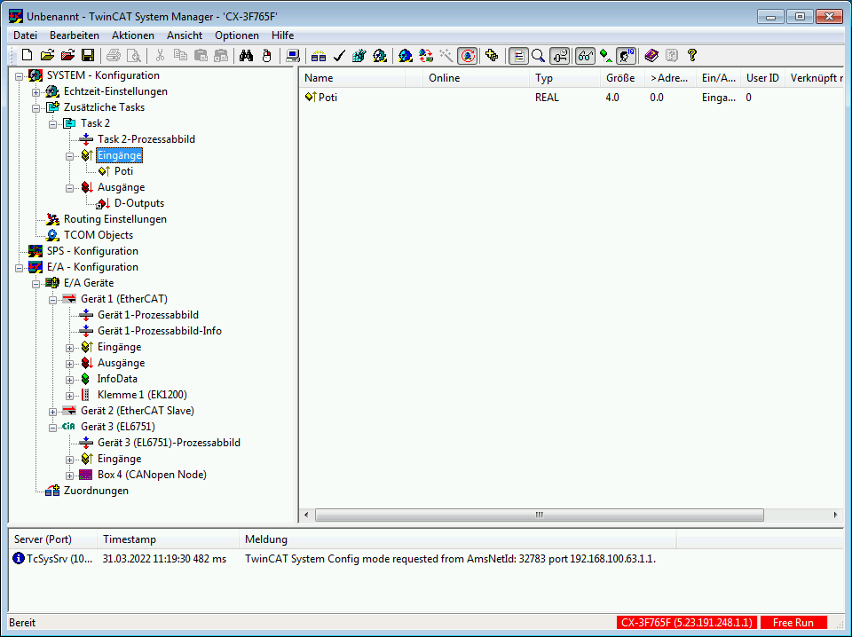
The I/O has actually already been fully configured with this step. What we have to do now is the mapping. To do this, I open “SYSTEM – Configuration” in the left tree of the TwinCAT System Manager and create a new task with the context menu under “Additional tasks”. I create new variables under the inputs and outputs of the new task. At the inputs I create a variable called Poti. I choose FLOAT as the variable type. I link this with the “Analog Input Float ADC0” input under TxPDO 2. This is our measured value of the connected potentiometer. I also set the settings “Swap LOBYTE and HIBYTE” and “Swap LOWORD and HIWORD” under Flags. This is necessary because the Siemens architecture interprets the values somewhat differently.
Under Outputs I create a variable of DWORD type with the name D-Outputs. Our 3 digital outputs are later located at bit positions 0..2 of this created variable. I link the variable with the process variable “Write Output Long1” from RxPDO 1.
As a last step, the created configuration must be activated. This works by selecting “Activate configuration…” under “Actions”. Now it is time to create the S7 program.
Development of S7 program
In this example I use the older Step-7 Manager from Siemens again. However, the functionality in the TIA Portal is similar. I first create a new S7 project and make the necessary hardware configurations. A more detailed procedure can be found in the IBHSoftec documentation. Before I start developing the S7 program, I first create a variable table to test the inputs and outputs.
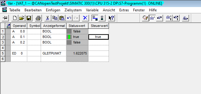
Because of the mapping I made in TwinCAT, I find my output states under O0.0 to O0.2. I get the current measured value of the potentiometer under ID0. If I now set O0.1 to true, the LED will light up redfor me. O0.0 is green and O0.2 is blue. If you move the potentiometer, you will find that the correct voltage value is already displayed.
Now we only need to write the user program and load it into the PLC.
Functional test
If I set a value higher than 4V with my potentiometer, the LED lights up red. If I turn it back a bit, it turns green again. If I set a voltage below 2V, the channel for blue is activated.
Conclusion
This example shows how you can connect a MELARECON IO to any PLC using CANopen. In the next post in this series, I will show you what else is possible with this intelligent IO module.