
MELARECON and CANopen
What is CAN?
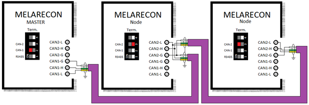
CAN stands for “Controller Area Network” and was originally developed by the companies Bosch and Intel as a bus system for vehicle technology. In the meantime, however, CAN has also proven itself as a field bus in the field of automation technology. The CAN bus is a serial bus system in which all connected stations (nodes) have equal rights. This means that each control unit can both send and receive and can therefore mutually exchange information. Due to the linear bus structure, if one station fails, all other stations are still fully available. To avoid reflections at the bus ends, these must be fitted with a terminating resistor. The MELARECON mainboard has corresponding DIP switches for this purpose, which can be switched on for the last participants.
The maximum bus length, i.e. the cable length between the first and last member, depends on the transmission speed. A transmission rate of 125kBit/s is factory-set on the MELARECON, which enables a bus length of 500m. However, this can be set as required on the MELARECON.
| Bit rate | Max. line length |
|---|---|
| 10 kBit/s | 6,7 km |
| 20 kBit/s | 3,3 km |
| 50 kBit/s | 1,0 km |
| 100 kBit/s | 600 m |
| 125 kBit/s | 500 m |
| 250 kBit/s | 250 m |
| 500 kBit/s | 125 m |
| 800 kBit/s | 75 m |
| 1 MBit/s | 40 m |
For optimal transmission, special cables suitable for CAN bus should always be used (e.g. Lapp UNITRONIC BUS CAN UL/CSA 2x2x0.5 2170267). The cable should contain at least three wires, two of which are twisted (for CAN-H and CAN-L). Furthermore, the line should be shielded.
| CAN line | Meaning |
|---|---|
| CAN-L (yellow) | Signal wire CAN-Low |
| CAN-H (green) | Signal wire CAN-High |
| CAN-GND (white) | Ground wire |
| CAN-VCC (brown) | Supply wire (optional) |
| CAN-SHLD | Shield |
With CAN, no stations are generally addressed, but the content of a message is marked by a unique number code (identifier). Messages are transmitted bit by bit on the differential line pair CAN-L and CAN-H. Two states (dominant = 0 and recessive = 1) are distinguished for the bit information. The figure below shows the general structure of a telegram.
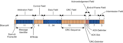
The structure of the telegram shows that it always begins with the identifier. This automatically results in a priority for a message on the bus. The smaller an identifier, the higher the priority of the telegram on the bus, since a 0 to be transmitted is always dominant.
What is CANopen?
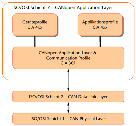
While CAN itself is only standardized for OSI layers 1 and 2 in ISO 11898, CANopen adds a layer 7 protocol to CAN. On the one hand, this defines the “how” of the communication, i.e. with which telegrams and which structure of the telegrams the devices can be addressed, and on the other hand the “what” of the communication is defined, i.e. what is the meaning of a setting on the device or which settings does it offer device at all. This is defined in device profiles or application profiles.
These so-called CANopen profiles are organized in table form (object dictionary). All device profiles have the so-called “communication profile” in common, through which basic device data can be queried or set. This can be the device designation, hardware and software version, error status and other parameters. The communication profile is expanded and defined by the device profiles with the device-specific settings and parameters. There are profiles for digital and analog I/O, drives, sensors, controllers, etc.
| Device profiles (CiA) | for device types |
|---|---|
| DS 401 | Digital and analog I/O |
| DS 402 | Drives |
| DS 403 | Operating and observing |
| DS 404 | Sensors / controllers |
| DS 405 | Programmable devices |
| DS 406 | Encoder |
| DS … | (other profiles) |
The object directory
CANopen describes the properties of devices in so-called device profiles. In principle, these are defined sets of variables. Depending on the device type, certain data or parameters are permanently defined in an object directory. This is a compilation of all variables and parameters (objects) of a CANopen device. The data contain the process image and the functional behavior of a CANopen device can be influenced with the parameters.
An object directory is structured in such a way that some parameters are mandatory for all devices in a category and others can be freely defined and used.
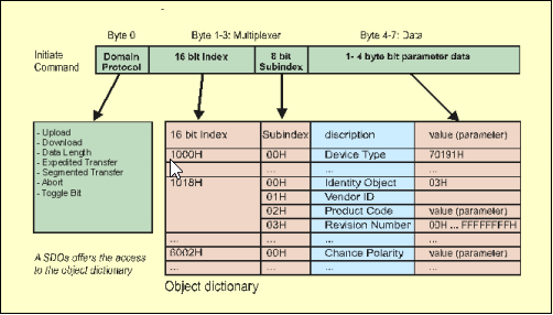
In CANopen, each object primarily receives a number (the so-called index) with which each parameter or object can be uniquely addressed. The objects can be simple data types such as bytes, integers, longs or strings. With more complex structures, such as arrays, the addressing of the individual elements is also implemented via a subindex.
The structure of the object directory, the assignment of index numbers and some mandatory entries are specified in the device profiles.
| Object Index (hex) | Object |
|---|---|
| 0000 | Not in use |
| 0001 – 001F | Static data types |
| 0020 – 003F | Complexes data types |
| 0040 – 005F | Vendor specific complex data types |
| 0060 – 007F | Device profile specific static data types |
| 0080 – 009F | Device profile specific complex data types |
| 00A0 – 0FFF | Reserved |
| 1000 – 1FFF | Parameters from communication profile |
| 2000 – 5FFF | Manufacturer specific parameters |
| 6000 – 9FFF | Standardized parameters from device profile |
| A000 – FFFF | Reserved |
| Index | Subindex | Name | Access | PDO-Mapping |
|---|---|---|---|---|
| 0005 | – | Dummy 8 | ro | Yes |
| 0006 | – | Dummy 16 | ro | Yes |
| 0007 | – | Dummy 32 | ro | Yes |
| 1000 | – | Device Type | ro | – |
| 1001 | – | Error Register | ro | – |
| 1002 | – | Status Register | ro | – |
| 1005 | – | COB-ID SYNC | rw | – |
| 1008 | – | Device Name | ro | – |
| 1009 | – | Hardware-Version | ro | – |
| 100A | – | Software-Version | ro | – |
| 100C | – | Guard Time | rw | – |
| 100D | – | Life Time Factor | rw | – |
| 100E | – | COB-ID Guard | rw | – |
| 1014 | – | COB-ID Emergency | rw | – |
| 1015 | – | Inhibit Time Emergency | rw | – |
| 1018 | Identity Object | |||
| 0 | no. of subentries | ro | – | |
| 1 | Vendor ID | ro | – | |
| 2 | Product Code | ro | – | |
| 3 | Revision Number | ro | – | |
| 4 | Serialnumber | ro | – | |
| 2000 | – | Device Manufacturer | ro | – |
| 6000 | Digital Input 8-Bit | |||
| 0 | no. of subentries | ro | – | |
| 1 | Digital inputs 1 to 8 | ro | Yes | |
| 2 | Digital inputs 9 to 16 | ro | Yes | |
| 3 | Digital inputs 17 to 24 | ro | Yes | |
| 4 | Digital inputs 25 to 32 | ro | Yes |
How does access to the object directory work with CANopen?
The data exchange in CANopen takes place in the form of telegrams with which the user data is transmitted. A distinction is made between the service data objects (Service data objects > SDO), which are used to transmit the service data from or to the object directory, and the process data objects (Process data objects > PDO), which are used to exchange current process states. There are also telegrams for network management and for error messages.
The entries in the object dictionary can be accessed with SDO. This is done according to the client-server principle. A device makes a request and the corresponding remote station replies. In practice, SDOs are mostly used for initialization during a boot process.
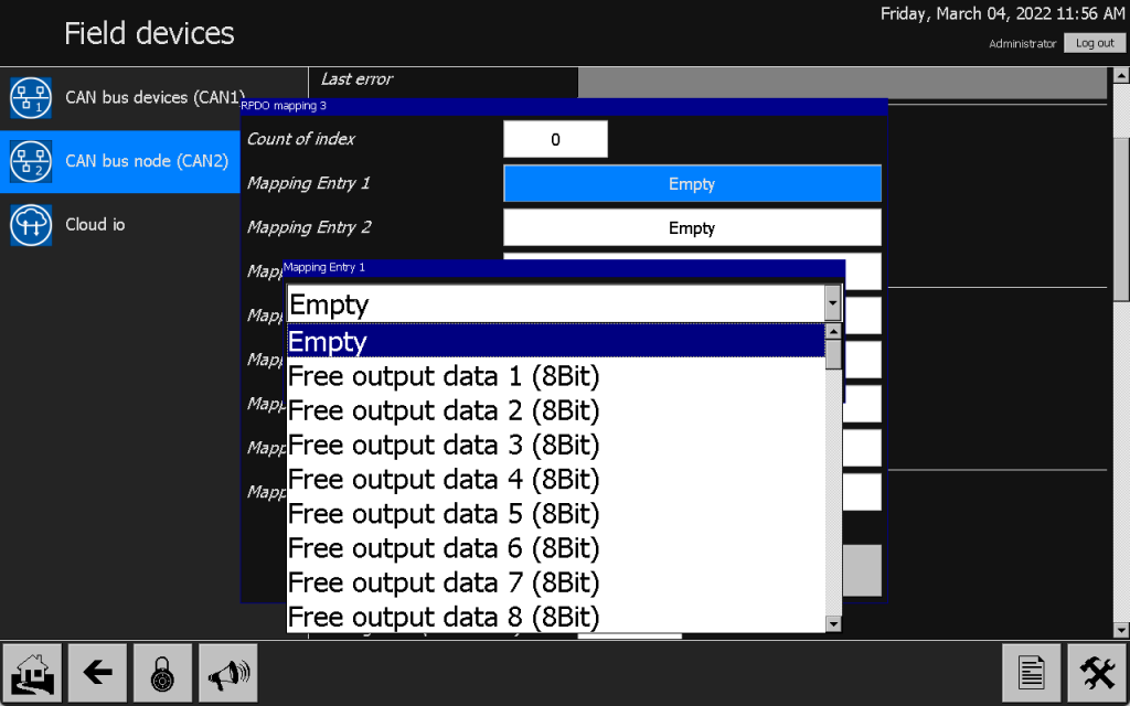
In principle, PDOs are a summary of various objects from the object directory, which are either sent cyclically, when the status changes, or by sending synchronization telegrams. A PDO can contain a maximum of 8 bytes. The content of a PDO can be freely configured (the so-called PDO mapping). In contrast to the SDOs, a PDO telegram is not answered and is therefore significantly faster.
| PDO | SDO |
|---|---|
| Real-time data | System parameters |
| Telegram is not answered (Fast Transfer) | Telegram is always answered (Slow transmission) |
| High priority | Low priority |
| Max. 8 bytes per telegram | Data can be distributed over several telegrams. |
| Pre-agreed data format | Index-addressable data |
With CANopen, multi-master capability is dispensed with in favor of network management and a CAN master (NMT master) is therefore introduced, which implements the tasks of network management. All other CAN nodes (nodes) are implemented as so-called slave assemblies.
A master controls the network by:
- Boot-up communication objects (start, stop, reset, etc.)
- Communication objects for node guarding or life guarding – This can be used to monitor the network
- Communication objects for synchronization
- Communication objects for emergency messages (Emergency)
In general, all identifiers are completely freely configurable. In order to save configuration effort, there is a default identifier distribution. This is defined in CANopen as follows:
| Identifier (binär) | Identifier (hex) | Function |
|---|---|---|
| 00000000000 | 0 | Network management |
| 00010000000 | 80 | Synchronization |
| 0001xxxxxxx | 81-FF | Emergency |
| 0011xxxxxxx | 181-1FF | TxPDO1 |
| 0100xxxxxxx | 201-27F | RxPDO1 |
| 0101xxxxxxx | 281-2FF | TxPDO2 |
| 0110xxxxxxx | 301-37F | RxPDO2 |
| 0111xxxxxxx | 381-3FF | TxPDO3 |
| 1000xxxxxxx | 401-47F | RxPDO3 |
| 1001xxxxxxx | 481-4FF | TxPDO4 |
| 1010xxxxxxx | 501-57F | RxPDO4 |
| 1011xxxxxxx | 581-5FF | SDO send |
| 1100xxxxxxx | 601-67F | SDO receive |
| 1110xxxxxxx | 701-77F | NMT Error Control |
So, to come back to the actual question asked above: How do you query an entry in the object register or how do you describe such an entry?
A CAN message is created with the identifier 600h + node ID (1-127 decimal) with a special data content. This message is sent and the corresponding partner replies with the identifier 580h + node ID and the corresponding data. The log of an SDO request looks like this:
How does PDO work?
Unlike SDO, there is no fixed protocol for PDO telegrams. A PDO only contains data and the data content is generally dynamic and can usually be viewed or defined via the settings of the communication profile (DS 301). A node differentiates between two PDO types:
- Tx: Output of process states to the network
- Rx: Receipt of process states from the network
When a PDO is sent or accepted by the node is also determined via the settings of the communication profile. There is the option of transferring process data in an event-controlled or time-controlled manner. The behavior of the individual PDOs can be set via the transmission type in the object directory (e.g. index 1400h; subindex 2). The table below shows the corresponding behavior.
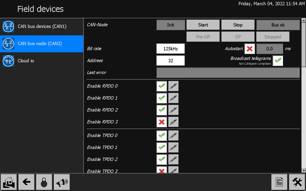
The content of a PDO can be viewed via indices 1600h – 1603h for received data and 1800h – 1803h for data to be sent. These inputs and outputs can also be edited via the display or via a remote connection to the MELARECON. To do this, go to the installation settings, then select the I/O configuration and then field devices and then CAN2.
Network management
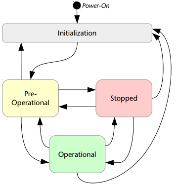
In a CANopen network there is a maximum of one NMT master, which takes over the organization in the network. This puts the individual network participants in different operating modes and usually takes over the initialization of the individual stations. There are four operating states:
- Initialization: State that each node goes through when it is switched on or restarted. After initialization, the node automatically goes into one of the other three states. This can usually be specified via the object dictionary.
- Pre-Operational: In this state (also called Pre-OP) communication with the node is only possible via SDO. PDO communication is not possible.
- Operational: In the “OP” state, the node is fully operational and can independently send and receive process data.
- Stopped: In the “STOP” state, the node is completely switched off from the network. Neither SDO nor PDO communication is possible. The node only listens to corresponding network commands. In general, the object register can be used to configure which states outputs should assume in this mode.
Functions of CANopen on the MELARECON
The MELARECON has two CAN bus connections. One of them (CAN1) is operated as an NMT master. Here it is possible to connect any CANopen device and to read and write its process data and service data. The CAN1 takes over the full network management from changing to the individual operating modes, through the initialization of the nodes to monitoring using node guarding.
The second connection (CAN2) is implemented as a complete CANopen node. This makes it possible to integrate the periphery of the MELARECON into an existing CANopen network and have it controlled and evaluated by a PLC, for example.